Ceramic Disk Capacitor Polarity

Capacitor Types Of Capacitors Fixed Variable Polar Non Polar Capacitors Diy Electrical Electrolytic Capacitor
Capacitor Polarity For Various Types Based On Its Markings
Polarity Learn Sparkfun Com
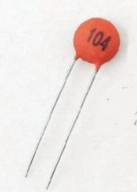
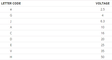
Ceramic Disc Capacitor Values Code Label
Is There Any Positive Negative Terminals In A Ceramic Capacitor 104 Quora

Electrolytic Capacitors Capacitor Symbols Macrofab

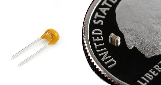
The ceramic capacitor is a non polarity device which means they do no have polarities.
Ceramic disk capacitor polarity.

How To Test A Capacitor Using Various Methods All About Engineering

Capacitadores Codigo De Valores Componentes Electronicos Electricidad Y Electronica Circuito Electronico

Capacitor Tips Re Antique Tube Radio Restorations

Capacitor Types Of Capacitors Fixed Variable Polar Non Polar Capacitors Diy Electrical Electrolytic Capacitor

Transistor Polarity Checker Electronics For You Transistors Simple Circuit Electronics For You
Do Polymer Electrolytic Capacitors Have Polarity Murata Manufacturing Co Ltd

Capacitor Types Of Capacitors Fixed Variable Polar Non Polar Capacitors Electrolytic Capacitor Diy Electrical
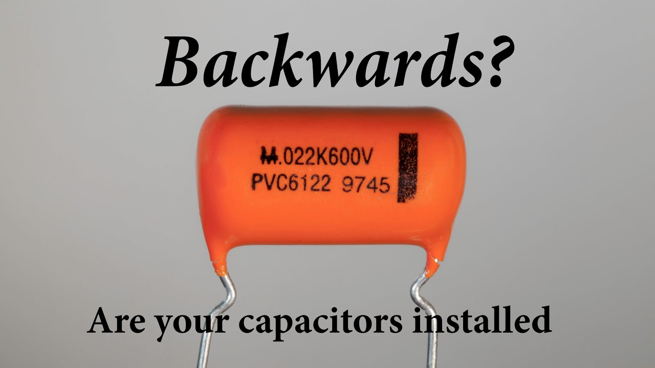
Are Your Capacitors Installed Backwards Build This And Find Out Youtube

Why Does Capacitor Polarity Matter Electrical Engineering Stack Exchange

Capacitor Types Of Capacitors Fixed Variable Polar Non Polar In 2020 Capacitors Polar Diy Electrical

The Basics 40 Exciting Solderless Labs Etron Circuit Labs

Axial Non Polarized Electrolytic Capacitors Capacitors
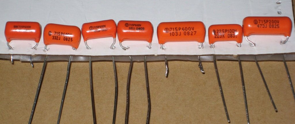
Tone Cap Polarity Revisited Planet Z
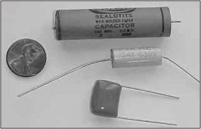
Antique Radio Classified Restoration Topics Dec 04 Cantelon

Capacitors In Audio Crossover Networks Application Notes By Electrocub
Smd Capacitor Working Polarity Types Identification Based On Codes
What Is A Ceramic Capacitor Common Uses Comparison Arrow Com Arrow Com
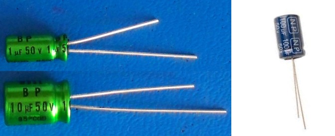
Non Polarized Capacitors
Https Encrypted Tbn0 Gstatic Com Images Q Tbn 3aand9gcshclq5evmwmxyp1we5xm1nf Sz0al1mjenadckne Q33l6w 0j Usqp Cau

Capacitors For Noise Filtering In Mini Quad Oscar Liang

Capacitor Lab Types Of Capacitors Radial Electrolytic Capacitors
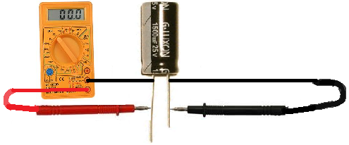
How To Test A Capacitor

Is It Possible To Replace A Ceramic Capacitors With Two Electrolytic Capacitors In This Configuration Electrical Engineering Stack Exchange

Types Of Capacitors Capacitor Types By Function Application
Source : pinterest.com
