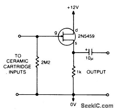
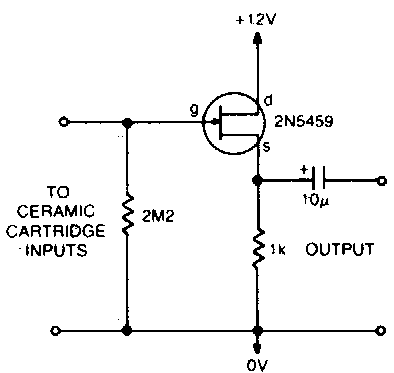
Ceramic Cartridge Preamp Circuit

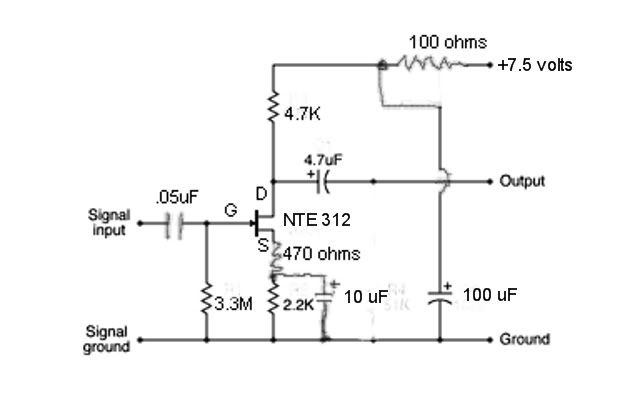
Ceramic Cartridge Preamp Circuit Pete S Mosfet Preamp

Ceramic Cartridge Preamp Circuit The Revitalizer

Ceramic Cartridge Phono Pre Amp Page 1 Phono Stages Step Ups Lenco Heaven Turntable Forum

Ceramic Cartridge Preamplifier Circuit Layout

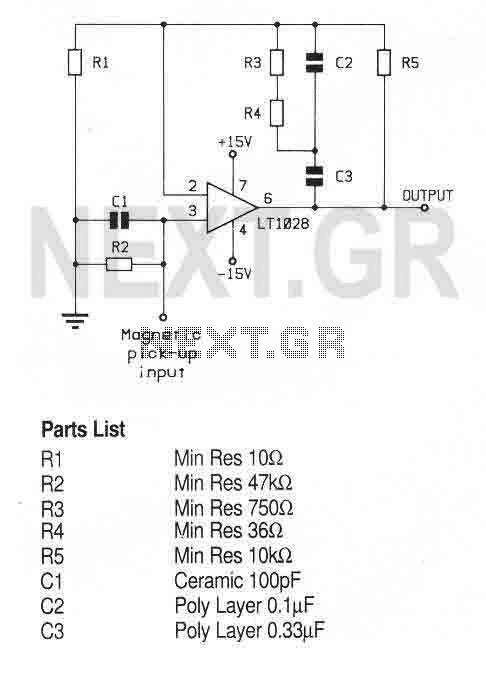
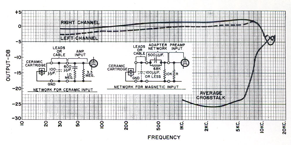
Preamp Equalization Network
Riaa Phono Preamplifier Using Lf353n

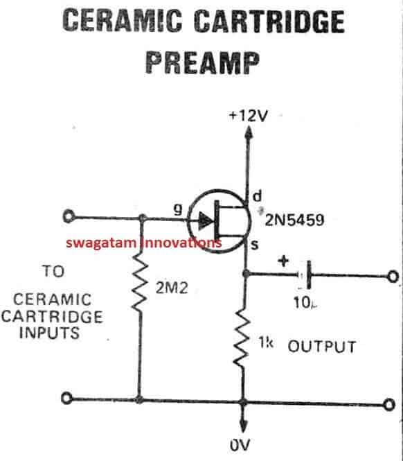
It utilises the 2n7000 mosfet transistor with minimal biasing overhead.
Ceramic cartridge preamp circuit.

Preamp Stage For Ceramic Phono Cartridge Or Violin Pickups Eeweb

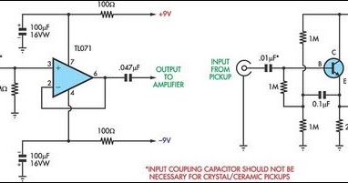
Preamplifier For Ceramic Pickup Preamplifier Circuits

Antique Radio Forums View Topic Preamp For Ceramic Cartridge

Simple Schematic For Using Ceramic Cartridges On Mm Phono Preamp Audiokarma Home Audio Stereo Discussion Forums
Preamp Stage For Ceramic Phono Cartridge Or Violin Pickups Circuits Projects
Using A Ceramic Cartridge With Modern Electronics Uk Vintage Radio Repair And Restoration Discussion Forum
Ceramic Cartridge Equalization
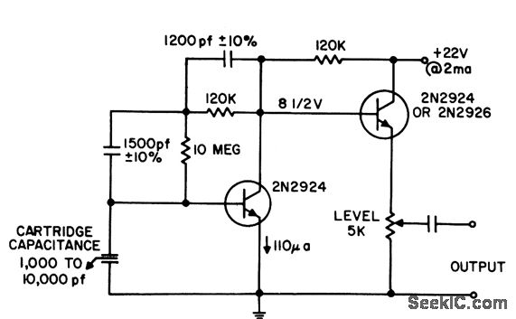
Velocity Response Phono Preamp Audio Circuit Circuit Diagram Seekic Com
Some Useful Audio Circuits
Preamplifier And High To Low Impedance Converter Amplifier Circuit Circuit Diagram Seekic Com
Audio Preamplifiers Circuits Audio Circuits Next Gr

Disc And Adamantine
Preamplifier And High To Low Impedance Converter Circuit Diagram Circuits Diagram Lab
Phono Pre Amp Circuit
Simple Phono Preamplifier Circuit Circuits Projects

New Member Old Topic Graham Slee Audio Forum Hifi System Components Page 1

Hi Fi Riaa Phono Preamp
4 Channel Dj Audio Mixer Circuit For Discotheque Applications Homemade Circuit Projects
Https Encrypted Tbn0 Gstatic Com Images Q Tbn 3aand9gctm2y9zmj51afcljznfjqhbqoql2lmej28c5c 7chz20f4ry1q Usqp Cau
Antique Radio Forums View Topic Calling All Crystal Phono Cartridge Experts

Grado Pre Amp Vinyl Engine
Curious Minds And Ceramic Cartridges Page 4 Vinyl Engine

Riaa Preamplifier Utilising Bc547
Pre Amplifier Audio Circuit Circuit Diagram Seekic Com
Source : pinterest.com
