Ceramic Capacitor Mtbf

Are There Any Methods For Estimating The Lifetime Of A Capacitor Murata Manufacturing Co Ltd

What Are The Failure Period Faq Tdk Product Center
Https Www Bqr Digital Com Bqrpc Examples Examplereport1 Pdf

What Is Mtbf Mean Time Between Failures Faq Tdk Product Center
Free Mtbf Calculator User Guide
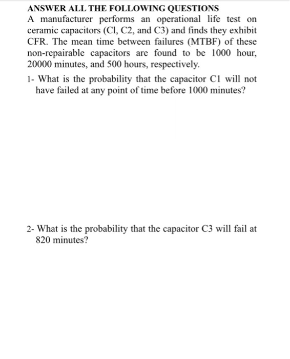
Solved Answer All The Following Questions A Manufacturer Chegg Com

Capacitors ceramic capacitors multilayer ceramic chip capacitors.
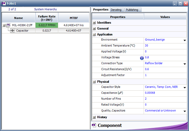
Ceramic capacitor mtbf.
Https Ec Kemet Com Wp Content Uploads Sites 4 2019 10 An1002 0715 Calculating Failure In Time Pdf

Ceramic Capacitor Murata Manufacturing Co Ltd

Wp Calculating Failure In Time Fit For Ceramic And Tantalum Capacitors Engineering Center

Ceramic Capacitor Reliability Data Request Venkel

Ceramic Capacitor 101 100pf Ceramic Capacitor Sigmatechbd
Http Catalogs Avx Com Advancedceramiccapacitors Pdf

How Hot Is Too Hot

The Basics Benefits Of Tantalum Ceramic Capacitors Passive Components Blog

Lighting For Life Digikey

Ceramic Capacitor Capacitors Ceramics Ceramic Materials
Mil 217 Bellcore Telcordia And Other Reliability Prediction Methods For Electronic Products Reliasoft

Reliability In Solar Inverter Design

Ceramic Capacitor 220 22pf Techshopbd Ceramic Capacitor 220 22pf Sigmatechbd Sigmatechbd

Reliability Passive Component Network Silicon Capacitors Murata Manufacturing Co Ltd

How To Read Ceramic Capacitor Values Capacitors Ceramics Reading

Capacitor Code How To Find The Value Of Capacitors Capacitors Electronics Basics Electronic Circuit Design

25 Avx Sr301c224kaa 22uf 220000pf 100v 10 Xr7 Radial Ceramic Capacitor Diy Tech Capacitors 10 Things
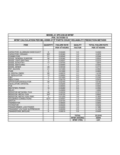
Model Xp2 230 20 Mtbf P N 10 74100 13 Copley Controls
Https Encrypted Tbn0 Gstatic Com Images Q Tbn 3aand9gcqfvwgqtvjk0uwpzziwgha4lcvhfn9y Rzkgnatbtlmsl1koqeq Usqp Cau
Http Www Radiant Su Files Images Novacap Reliabilityguide Pdf
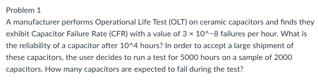
Solved A Manufacturer Performs Operational Life Test Olt Chegg Com

Capacitor Code How To Find The Value Of Capacitors Capacitors Electronics Basics Electronic Circuit Design
Https Atceramics Com Userfiles Uploads Pdfs Rf Power Amps W600 Series Pdf

Capacitor Types And Performance Element14
Source : pinterest.com
